
Predictive maintenance for reducers
How do you catch reducer wear before a seized stage stops the machine it drives?
A reducer turns speed into torque, and every stage concentrates load onto its gears and bearings.
Gear mesh wear, bearing wear and misalignment each leave a distinct mark in the spectrum, so the reducer tells you what is wearing and where.
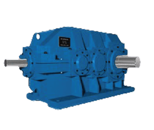
Typical faults
Worn or pitted teeth show up as sidebands around the gear mesh frequency, spaced at the shaft rotation speed. The sidebands grow with the wear and are visible in the spectrum long before the wear is audible.
Reducer bearings carry the mesh reaction forces of every stage. Wear raises the high-frequency noise floor, then adds discrete peaks at the bearing characteristic frequencies.
A misaligned input coupling shows a strong peak at twice the rotation speed and pushes uneven load onto the first-stage teeth.
Loose foot bolts or a soft foot let the reducer rock on its base, producing a train of rotation-speed harmonics.
Where sensors go
Sensors are bonded next to the bearing seats — no machine modification. Each sensor is bound to its measuring point in the app with a tap, and the gateway is wall-mounted nearby.
DT310 wireless vibration and temperature, 3-axis, 0–6000 Hz. Use DT311, with an external antenna, where a point sits inside an enclosed metal structure.
DMG310 (Ethernet / Wi-Fi): up to 60 sensors each, 60–80 m range in a typical plant (about 300 m line of sight). DMG311 (4G / Ethernet) for sites without Wi-Fi.
How to read a typical spectrum
A healthy reducer shows the gear mesh frequency of each stage with small sidebands. Worn or pitted teeth grow sidebands around the mesh frequency, spaced at the shaft rotation speed — the same signature as a gearbox, read on the slower, torque-dense machine.
Questions
How many sensors does one reducer need?
Typically 4: input and output shaft bearing seats, plus the motor drive end and non-drive end.
What is the difference from monitoring a gearbox?
The signatures are the same — gear mesh, bearings, misalignment — read at lower speeds and higher torque. The AI adapts the analysis to the machine.
Can I start with just the reducer?
Yes — plans start from one sensor per machine, and you add sensors where a machine has more measuring points. See the help centre for the measuring-point plan.
Map the measuring points on your equipment before the first call.