
Predictive maintenance for hoists
How do you catch gearbox wear in a mine hoist before it risks a shaft trip?
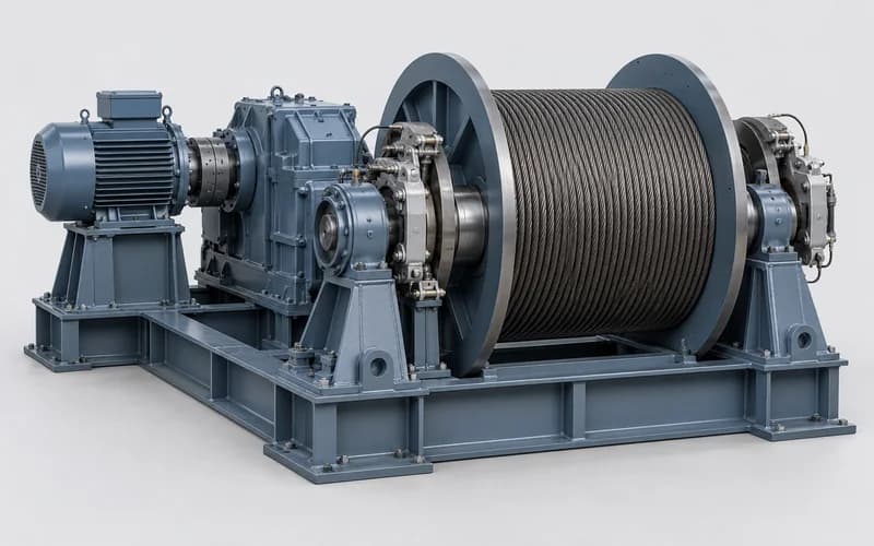
A hoist lifts people and material, and its gearbox, bearings and drum are safety-critical.
On the gearbox and motor, gear mesh wear, bearing wear and misalignment show up in the spectrum long before they are felt.
The slow drum is watched through its vibration and temperature trend, and only captures taken at steady running speed are compared, like for like.
Typical faults
Worn or pitted teeth on the gearbox input (high-speed) stage show up as sidebands around its gear mesh frequency, spaced at the input shaft speed, that grow over time. Only captures taken at steady running speed are compared, and a higher mesh peak on its own can come from load or alignment, so the sidebands are what to watch.
Hoist bearings carry the full rope load. On the gearbox and motor, wear raises the high-frequency noise floor, then adds discrete peaks at the bearing characteristic frequencies. The slow drum bearings are watched through their vibration level and temperature.
A misaligned motor–gearbox coupling shows a strong peak at twice the shaft speed and loads both bearings unevenly. Misalignment at the slow drum end shows as a rising vibration and temperature trend at the drum bearings.
Loose foot bolts or a soft foot on the gearbox or motor base produce a train of shaft-speed harmonics.
Where sensors go
Sensors are bonded next to the bearing seats — no machine modification. Each sensor is bound to its measuring point in the app with a tap, and the gateway is wall-mounted nearby.
DT310 wireless vibration and temperature, 3-axis, 0–6000 Hz. Use DT311, with an external antenna, where a point sits inside an enclosed metal structure.
DMG310 (Ethernet / Wi-Fi): up to 60 sensors each, 60–80 m range in a typical plant (about 300 m line of sight). DMG311 (4G / Ethernet) for sites without Wi-Fi.
How to read a typical spectrum
A healthy hoist gearbox shows the input-stage gear mesh frequency with small sidebands at the input shaft speed. Worn or pitted teeth make those sidebands grow over time; a higher mesh peak on its own can come from load or alignment, so the sidebands are what to watch — the sensor samples on a fixed schedule and captures taken at steady running speed are compared like for like, so the warning comes while the gearbox still has life left.
Questions
How many sensors does one hoist need?
A typical start is 5: gearbox input and output, two on the drum bearings, and one on the motor drive end.
Does monitoring add a safety burden to the hoist?
No — sensors are bonded next to the bearing seats with no machine modification, and there is no change to the hoist's safety systems.
How often is the hoist diagnosed?
On the AI Care plan, Mina runs an automatic diagnosis on every machine each day, and an alert is raised when a change is confirmed. See the help centre for the full cycle.
Map the measuring points on your equipment before the first call.